1968 Imperial Crown Project
Instrument Panel Restoration: Adventures in Pain
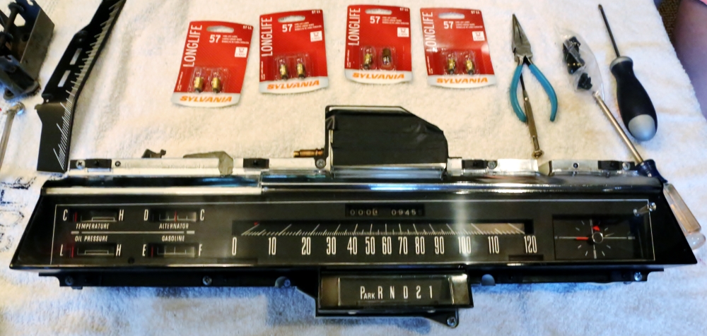
CLOCK | DASH DIMMER SWITCH | TRIP ODOMETER AND CLUSTER REASSEMBLY | LED LIGHTING | SAFEGUARD SENTINEL | BRONZE REFINISHING
I suppose I had to start somewhere.
After fixing the fan clutch, I decided to tear into the instrument panel. There were lots of reasons to do this. The high beam indicator lamp and most of the instrument lights were out. The clock didn't work. The trip odometer did not work. The dash light dimmer did not work. The Safeguard Sentinel would turn the lights on but they stayed on even in bright light. The bronze trim was scratched and tarnished. I found all of this frustrating.
So I started by disassembling the instrument panel. I didn't take pictures along the way but I just followed the instructions in the factory service manual. Without elaborating too much for fear of discouraging the more ambitious of you out there, I will say that pulling the cluster out of a Corvair is child's play compared to this sucker.
The first repair I made was to the clock. I have three other old cars and used to own a fourth, and in each of them I have replaced the old Borg mechanical movement with the quartz movement manufactured by Instrument Services, Inc. The same ISI movement fit both of my Corvairs, my '63 Olds Ninety Eight, my '68 Cutlass and the Imperial. I have been running these in multiple cars for, collectively, probably around 25 years and never had a problem with one failing or keeping time poorly, so as far as I am concerned, there's no point in keeping the old mechanical movement in the car.
Unfortunately I don't have photos regarding the clock install but it's pretty straightforward to do these. The clock kit comes with directions and an instructional DVD. I bought mine on eBay from ISI for $75. Their seller name is clocks4cars and the kit is no. S-3015. The biggest Corvair vendor, Clarks Corvair Parts, used to sell this kit for $35-40, and it's universal, so I checked their page. They now want $98 for the part, so buying direct is the best bet, and it's clear ISI either had some supplier increases or decided their part was under-priced. Since I paid the new higher price, I guess they were right on the under-pricing thing.
Once you have dug the clock out of the dash, you can start replacing the movement. All of these clocks were assembled pretty much the same way. The hands press on and can be pulled off. Be careful not to bend or break the hands, especially the second hand, as you remove them. Once the hands are off, you can remove the face, which is light aluminum and is held in with bent over tangs. These can be easily straightened with a screwdriver. The next step is the fun part. The front of the clock housing is a flat piece of metal that is held in place by three creases into the case that bend the lip over the front of the case. Get a hammer and a big screwdriver and you can straighten the lip of the case so that the clock can pull out. You will also have to remove the nut on the back of the case that holds the terminal for power. Then the clock will pull out.
The clock has three posts that hold it to the face. They go through three rubber bushings and are held in place by three round snap clips. Pry these off with a small screwdriver and the clock should come free of the face.
The kit comes with two sets of gears, one black and one red. You need the red gears. Assemble them to the clock using the existing washers and gears from the original clock as shown in the illustration that comes with the clock. The kit comes with new retaining clips. Install the clock with gears to the face, and then just reverse the procedure from there.
DASH DIMMER SWITCH
This was another throw-money problem. Apparently these dimmer switches are prone to failure. A seller on eBay, devinism, offers a rebuilding service with improved connections and a (more or less) lifetime guarantee for another $75. The dimmer switch was removed and sent for repair. It's now back in the switch panel awaiting for the panel to go back in the car.
TRIP ODOMETER AND CLUSTER REASSEMBLY (Updated June 17, 2013)
After disassembling the cluster I found that one of the number barrels on the trip odometer was cracked. I took the unit to Bob's Speedometer, a restoration shop in Howell, Michigan. They told me that the repair would run from $400 to $500. I promptly ordered an NOS speedometer that was listed on eBay for $200.
One of the guys at Bob's laughed at me and said, "I bet you had fun getting that out," pointing at the cluster in my hand. Better me than him, I am sure he was thinking.
I did leave the instrument cluster lens with Bob's for polishing and touch-up to the PRNDL indicator, which had been worn by the shift indicator. They said that they might charge me $100 to reset the odometer on the new speedometer to the original mileage. I said I would think about it.
Today, June 17, was a big day for deliveries at the office. The lens came back from Bob's, the chemicals for refinishing the bronze arrived, my sockets for the gauge backlights arrived (more on that later), and the speedometer showed up.
The speedometer was a problem. The seller had packaged it very carefully, but it looks like the package was slammed very hard in transit and the needle and backplate were bent pretty badly. Looking it over, it may have been NOS, but it looked like it had spent the last 45 years on the shelf outside of any box in a pretty dirty environment.
I contacted the seller immediately. He suggested that if there were parts that were useful to me to make an offer; otherwise he would refund my price and shipping costs. I offered $50, he countered at $70 and we had a deal. So now I stood at $70 invested instead of $400 plus, but I would have to supply the labor.
Fair enough.
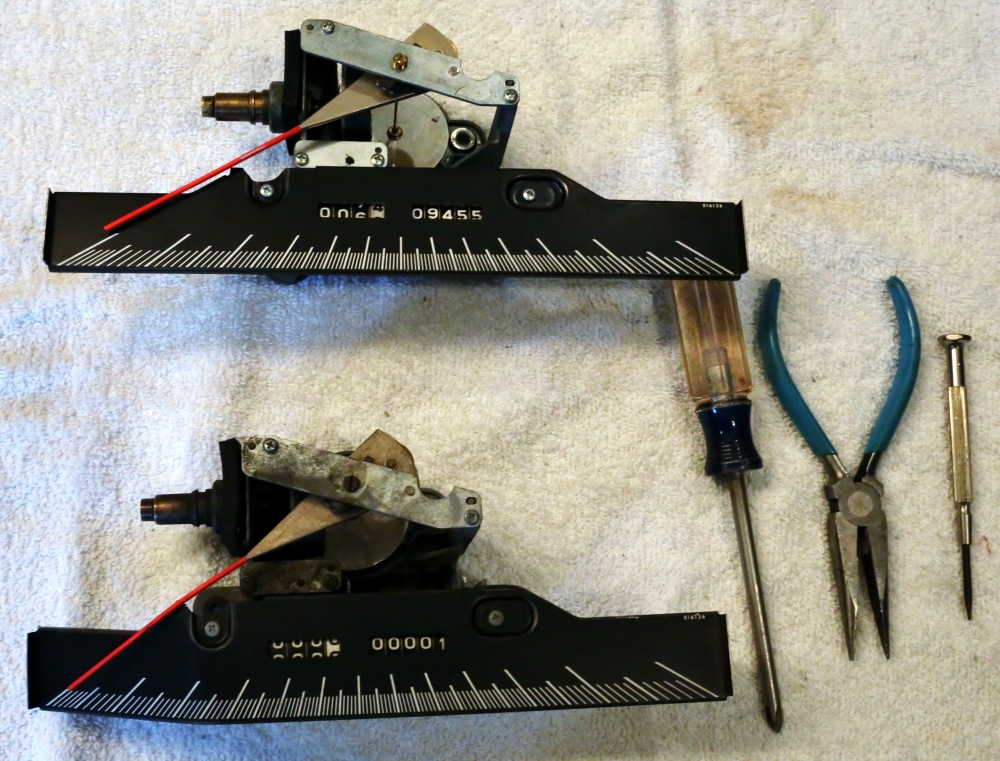
I gathered up the speedometers and the tools. Given the condition of the "new" speedometer, I figured that the best bet was to just pull the odometer wheels from the damaged speedometer and install them in my original speedometer. Here's a picture of both speedometers, with the original one at the top. When removed from the car, my odometer was at 09455 miles.
The first task was to disassemble the donor speedometer. Two phillips screws are removed to take the backplate off. Once that is out of the way, there is a snap ring on the right side of the odometer shaft that must be removed. The snap ring holds a bushing in place. Once the snap ring is gone, the odometer assembly can be lifted out of the speedometer frame.
The next task was resetting the odometer to the car's actual mileage. Each wheel on the odometer has a fork that engages the edge of the speedometer frame. There are gears between the wheels that prevent them from freewheeling so that the odometer works correctly.
After quite a bit of trial and error I found that the way to reset the odometer was to work from the right to the left. First, use the geared wheel on the right end to turn the singles column to the correct number facing up when that wheel's fork is pointing down in the right position. This picture shows the forks:
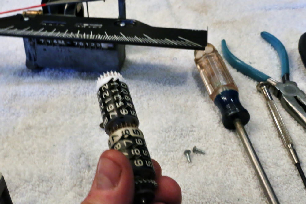
You can see the forks in place on the original speedometer in the background.
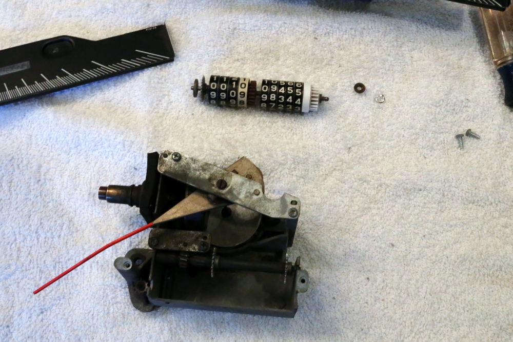
While holding the singles column and its fork in place, roll the tens column counterclockwise, as viewed from the right end of the odometer. As the fork for the tens is coming over the top, stop turning the wheel and pull the fork ahead a little bit. Each full rotation of the wheel will advance the tens digit by one. Continue to do this until the correct number lines up with the singles digit when the forks are both properly aligned. Continue this process down the row. I believe that the last digit rolls the opposite direction to set the number. This picture shows the odometer assembly removed and reset, with the bushing and snap ring next to it:
To reinstall the odometer, tip the right end up so that the gear on the left end can clear the trip odometer reset gear on the left side of the speedometer housing. carefully line up the forks for each wheel. I didn't worry about what the trip odometer was reading because I figured the reset mechanism would be working soon.
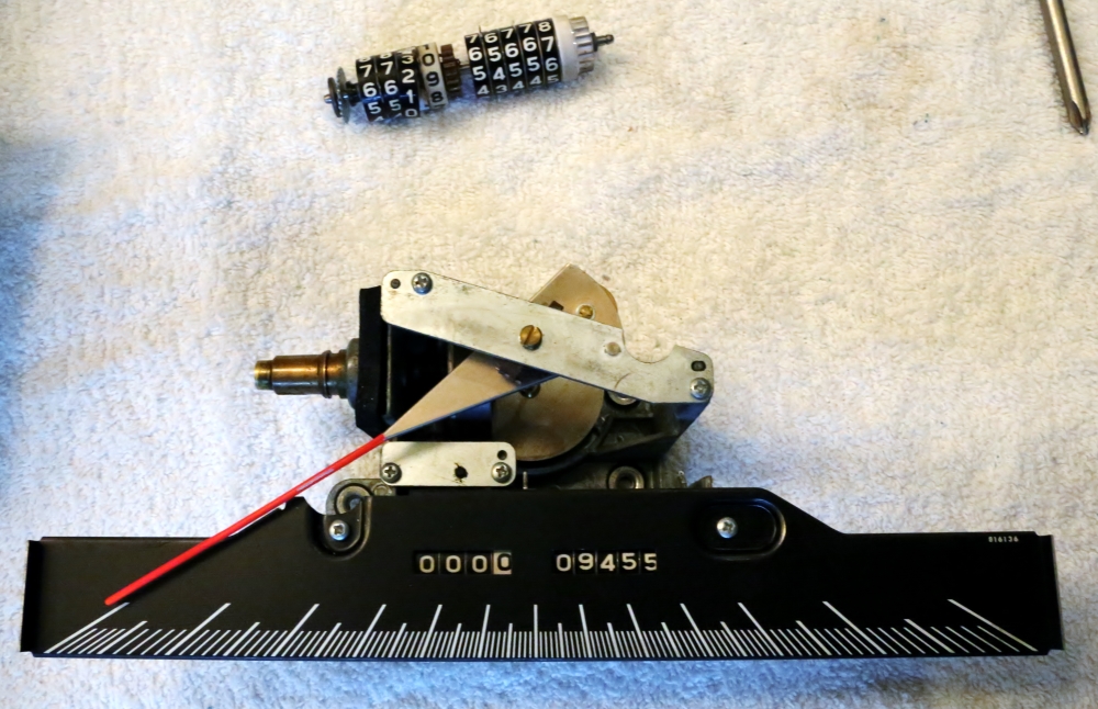
I followed the same procedure to remove the odometer from the original speedometer and install the new odometer assembly. I tested the trip reset mechanism and it worked. Here is a picture of the reassembled speedometer and the damaged original odometer assembly. If you look closely you can see that the singles digit wheel in the trip odometer has split in two.
Next, I installed the speedometer back into the cluster. The screws weren't super-tight coming out because the speedometer has soft rubber mounts, so I just tightened them to snug, as they were when I removed them. I carefully dusted the plate that goes over the gauges. I was impressed that this was a heavy diecast piece; I was expecting plastic. This is held in place with eight screws.
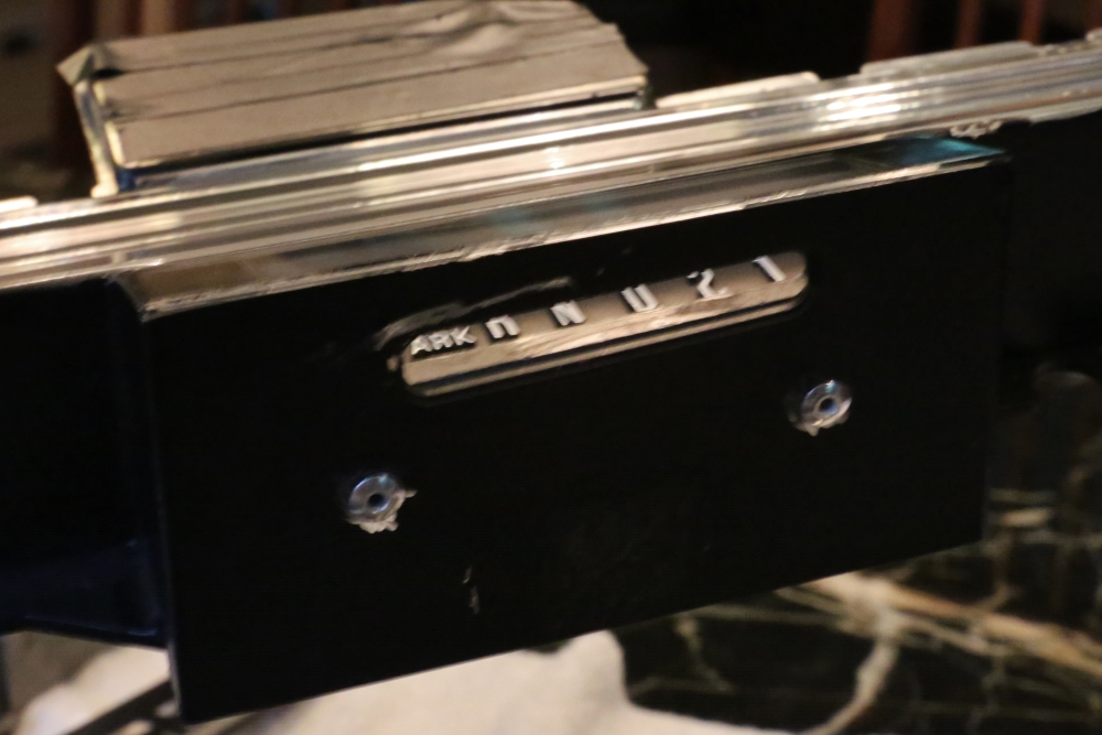
Bob's had removed the PRNDL indicator by grinding off the rivets and repainted the lettering on the indicator face. They then re-riveted the indicator into place:
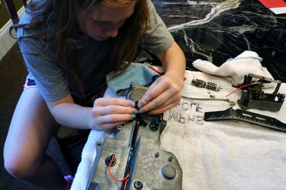
Caitlin and I then reinstalled the lens using the original eight clips. We screwed the clock reset handle back on and this is how it looks:
New quartz clock, fixed odometer, touched up selector indicator, and next, working illumination. Caty and I installed new light bulbs. I have been debating about installing LED bulbs but at this point I think I have more money into this project than I had intended. I am sure I will regret this later, but for now I am just replacing all of the incandescent bulbs with new. There's still time to change my mind because the rebuilt dimmer switch isn't back yet....
When I pulled the cluster, I found that one of the two bulb holders behind the gauges was missing. These little holders are commonly used today, but only with the flat 194 style bulbs; after quite a bit of searching I could not find holders that would take the 57 style brass base bulbs. So I purchased two new holders of the 194 style and will pick up bulbs for them tomorrow.
LED LIGHTING (Updated June 25, 2013)
Forget what you just read. I changed my mind and decided to go with LED lights for the instrument cluster. I decided to buy from a seller on eBay who had a very good price and spent about $50 for too many bulbs. A couple of comments are in order. First, there are two twist lock bulb holders on the left side of the panel. Unlike a conventional light bulb, LEDs are diodes and therefore have polarity. Do whatever experimentation you need to do with the bulbs to make sure they are in correctly before you reinstall the panel or there's a 50/50 chance per bulb that you will regret it.
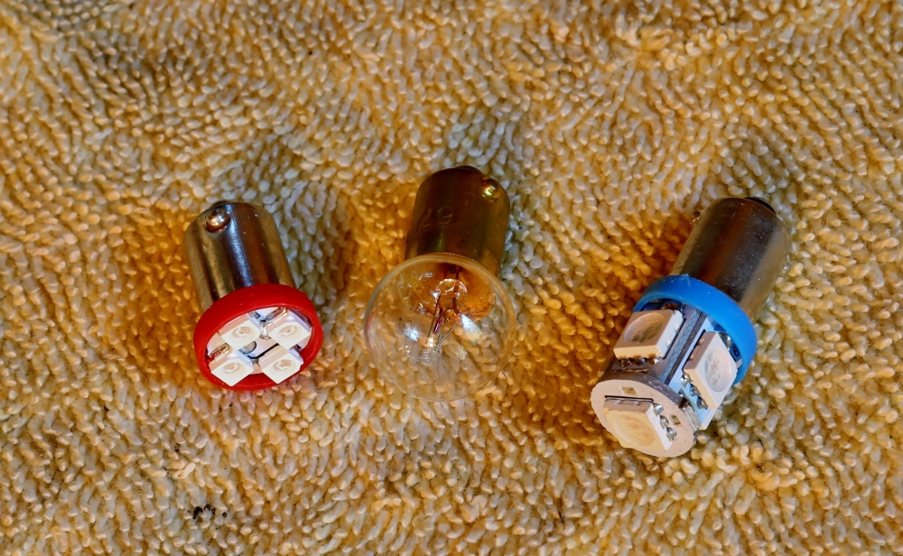
The LED lights come in a variety of sizes. There are little towers that have five LEDs, little towers that have nine, flat bases that have four.... For the background lights on the dash, the five tower lights seem like a good replacement. These are a little brighter than stock, which I think is nice, and they are cheaper than the nine LED towers.
For the red warning lights (brights, Sentinel, and brakes) I used red flat four- LED units. These are perfect.
The advice I have seen on-line is to go with blue bulbs for blue lenses, red bulbs for red lenses, etc. I don't think I am going to follow this advice as to the background dash lights, and I will show you pictures so you can judge for yourself.
Here is a picture of the different bulbs with a stock incandescent for comparison:
Here is a picture of the dash with all blue LEDs:
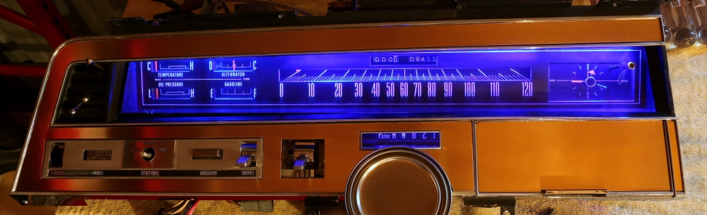
I laid the panel over the cluster to block stray light. I think it's way too blue. The picture isn't an exact match, but the white lettering seemed harder to read, and this is obviously not stock lighting. It is cool but it would seem more appropriate in a Honda CRX than here.
For a comparison, I replaced the two lights next to the clock with two new stock incandescent bulbs. This is what I got:
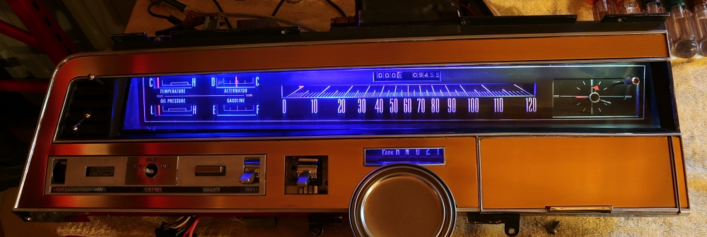
From this you can compare both appearance and light levels. There is a very subtle hint of blue in the stock lighting, but not much. I think the amount of light you get from these LEDs is more than adequate.
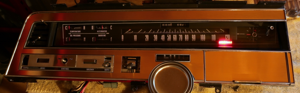
The next picture shows the red LED in the brake light socket. The picture doesn't do the bulb justice. It appeared as a deep, bright red. It will get your attention without blasting your corneas out of the back of your head.
So that's the way I see it. I am going to order some white LEDs and then go work on refinishing metal. Oh, by the way, the rebuilt dimmer switch came today....
June 28, 2013 Update
My white LEDs came today. I think these look much, much better. I also hooked up the switch title light to see how it looked. The light bulb does not fit with the blue lens in place but if you press hard enough you can break the tab that holds the blue lens in place. Since the lens is missing, at least for now, I tried a blue LED and a white LED. The blue was definitely wrong. Here is a picture with the white LED:
The contrast in color is more striking than the photo suggests. So either I go with white switch titles and blue instrument panel, or I find a way to make the lens fit.
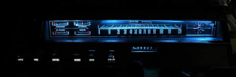
Just for comparison sake, I took a picture with the room lights on. Here is that picture followed immediately by the blue LED panel:
I know it's a matter of taste, but the white LEDs look right to me. My eBay seller doesn't accept returns, so I have a nice surplus of blue bulbs for when I get my Honda. If ever.
June 30, 2013 Update
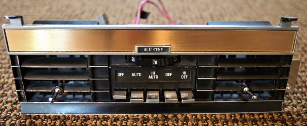
Next lighting issue to tackle was the climate
control head. I am glad I decided to do this one now because getting this
sucker out is a royal pain and would almost certainly lead to damage to my
(eventually) refinished bronze. The first step was to remove the climate
control unit. This is more fun than a barrel of monkeys. Seriously, can you
imagine having a barrel of monkeys? Anyway, you remove the plastic plate under
the dash brow above the control unit (hopefully without dropping the screws
into the A/C vents), remove the vent control slider from the plate using a
really short screwdriver and again hopefully not dropping the screws into the
abyss, take out the four screws holding the control unit in place, and then
wrestle with it every which way until the unit kinda slides out. Then you cram
a stubby screwdriver up above it, remove the two screws that hold on the A/C
ducts, dangle the unit from its wiring until you break one of the wires that
goes to the temp rheostat, unplug all the wires, unclip the vacuum lines (all
while hoping that they don't turn into random spaghetti) and just like that,
the control head is out. No, don't throw it across the garage, as this may
damage it and/or the car it hits.
Now it's time to change the bulb, right? Wrong. Now it is time to disassemble the unit because you can't get to the bulb without doing that. Look, see the bulb in this picture?
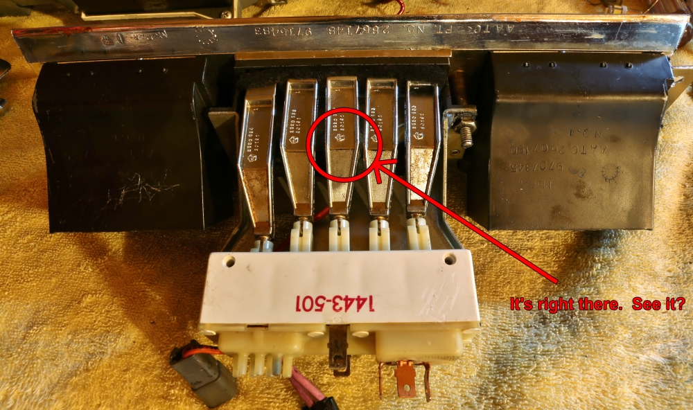
I don't, either. I see the wire disappearing in there.
So flip the unit over, and remove these two screws so that the controls can be removed and then you will have access to the light. Yes, it's just that simple.
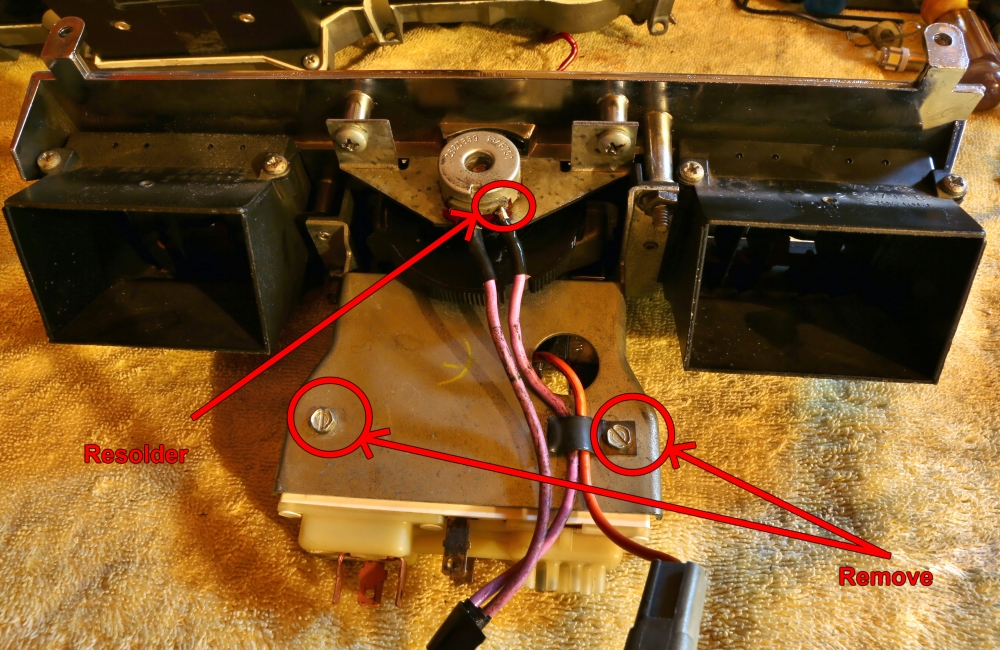
Since you have everything apart, you might as well unscrew the temp rheostat and run some tuner cleaner through it to make sure that the rheostat stays healthy. Protect your solder job by trapping the repaired wire under the clip that attaches to the light wire when you reassemble the unit. When you're done, it should look like this:
You will notice that I have stripped this piece of bronze. I also pulled and stripped the piece that goes on the radio door. I am so frustrated with the bronze project that I am going to try to hire my paint guy to do it. (I just realized that if someone reads this page from top to bottom, this will seem somewhat schizophrenic since I discuss bronze refinishing somewhere down below, but I am now kinda committed to the format of this page, which is getting immense. Next time I will return to my usual day-by-day format instead of trying to do the discussion by topic. Live and learn, right?)
I tried to find the light bulb in the radio. I honestly did. I think I have to take the radio out to get at that one. It would make no sense to put it where it could be accessed easily. After all this, I decided to just go steel wool bronze for awhile.
When I replaced this bulb I noticed that the lighting is significantly more blue than the switch titles on the instrument panel, where I am currently missing the blue bulb because I broke that, too. So I ordered some flat 4-LED lights like the red ones above, only white. I will JB Weld the lens back in place and use the white bulb for the switch titles. That will give me the correct blue light I so crave.
Even though the bronze thing is driving me NUTS I am loving the look. This car is going to be so freaking cool when I get it put back together. In 2015.
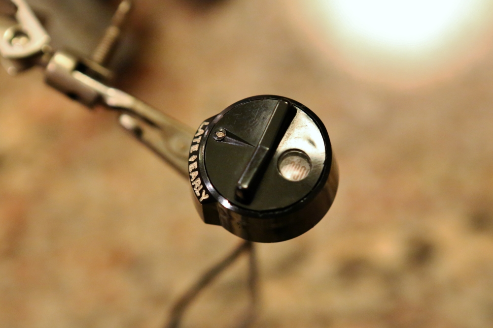
SAFEGUARD SENTINEL (Updated June 13, 2013)
After asking around on the Imperial list, I came to the conclusion that the sensor on the dash had failed in the on position. Maybe I am wrong, but from what I have read, these sensors have a tendency to go bad. I learned from Chris Sculthorp that the sensor is a light detecting resistor, or LDR. I decided that now would be a good time to remove and replace the LDR, since access is pretty easy with the dash removed.
There are two wires coming from the sensor and a connector just below the sensor. This needs to be unplugged. After unplugging the connector, it is necessary to remove the connector housing because it will not fit through the hole in the dash. (The service manual says to just cut the wires, but this is a bad idea since I want to reuse the housing and wires.) Each of the blades in the connector are held in by a barb that is part of the blade of the connector. This barb can be pushed in with a screwdriver, and then the wire and connector can be pulled out of the connector housing.
There is a spring clip that holds the sensor housing in place. This can be pried away from the tapered bottom of the sensor housing with a screw driver. Once the clip is free, the sensor can be removed from the dash board.
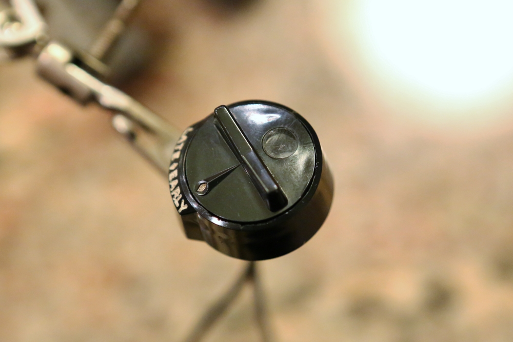
The top of the sensor is a rotating piece used to adjust the sensitivity of the system. It just contains a window that allows more or less of the LDR to be exposed. It lifted right of of the sensor housing. This picture shows the pieces you should have at this point:
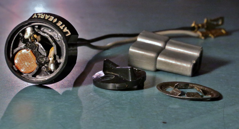
From this picture you can see the LDR, with a cracked surface, the cover for the sensor housing, the connector housing, the spring clip that holds the sensor housing in place, and the leads coming off of the sensor housing. You can also see that the factory held the wires for the LDR and the LDR itself in place by swedging over the plastic of the housing. This will not be an option with reassembly, so I will have to glue the sensor in place.
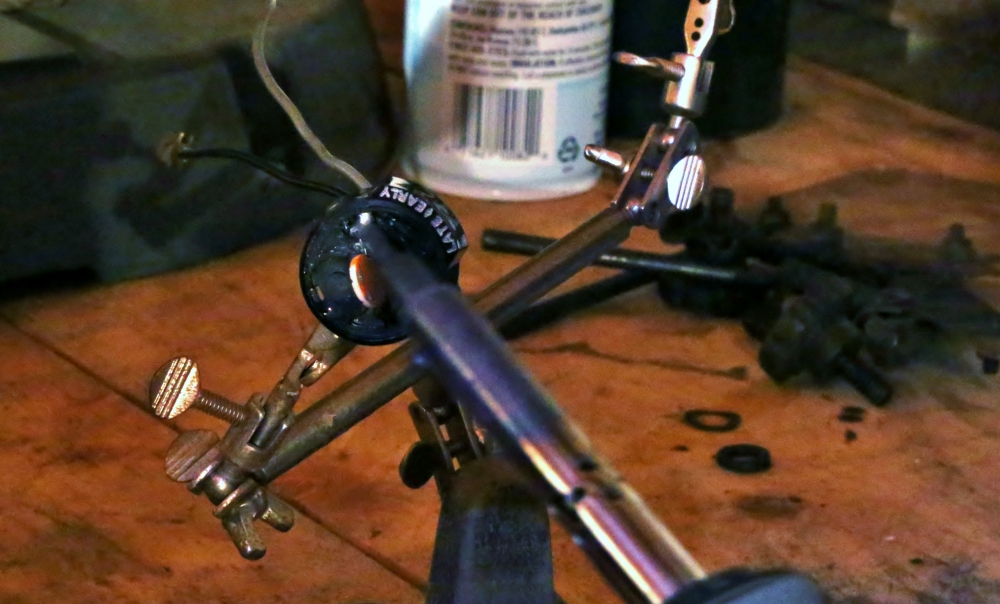
The swedged-over plastic can be removed by carefully picking at it with a knife. Once the plastic is removed, you can pry the LDR out like this:
.jpg)
The next step is to heat up the two solder connections with a soldering iron so that the LDR can be removed.
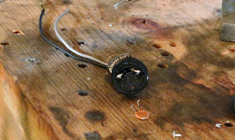
Here is a picture of the LDR after being removed from the housing.
Once I got the photocell out, the next step was to replace it with an appropriate part.
There is some conflicting information out there, but I think that I have it sorted out. First, there are three types of electrical components that respond to light: photoresistors, photodiodes, and phototransistors. The Imperial Club's archives suggest that this device is a photodiode. Specifically, this is what appears on that page:
It is not strictly speaking a switch, however, it is a variable resistance photodiode, which drops in resistance when it "sees" light. It is connected to a resistance level sensing circuit, which "trips" the lights off when a threshold is reached. This makes the device very easy to repair, at least if the failure is the most common one, namely failure of the photodiode. These are dirt cheap, and in fact come in an assortment package for a few bucks from Radio Shack. I think the threshold resistance is somewhere around 500 ohms, so pick one from the assortment which shows a "dark" resistance of 1500 Ohms or so, then use the variable lens cover to adjust it so that the lights come on at dusk. I did this 14 years ago when I first got my 68, and it still works perfectly.
This quote was very helpful, but it's not entirely accurate. First, I think that the sensor is not a photodiode but a photoresistor. There are several reasons for this. First, it looks like other photoresistors I have seen and does not look like photodiodes I have seen. Second, the factory shop manual says that it does not matter which color wires are connected to which when reinstalling the sensor. This would only be true with a resistor as diodes have polarity; they have very low resistance in one direction, but very high resistance in the other. Finally, photodiodes respond much more quickly to changes in light. This would be a disadvantage in this application, where it would be better to have the sensor respond slowly, rather than flicking the lights on and off every time the car passed through a shadow.
A second error in this text is that it talks about "dark" resistance. This should refer to "light" resistance. This circuit works backwards; when there is current flowing through it, the lights are OFF; when the circuit is open (no current), the light activates. This was dictated by the nature of photoresistors. The factory shop manual indicates that to test the photocell, you should jumper across the leads to the photocell. This would create a resistance of zero and should turn off the lights. So when the sensor is "dark" the impedance should be infinite. As light hits the sensor, at some point it will cross the threshold the amplifier is looking for and complete the circuit as resistance in the circuit drops. This signals the amplifier to shut the lights off because it is daylight out.
Having thought this through, I went to Radio Shack and was able to purchase an assortment of five photoresistors for $4.
Caitlin and I then got out some tools. First, we checked the resistance of the original sensor.
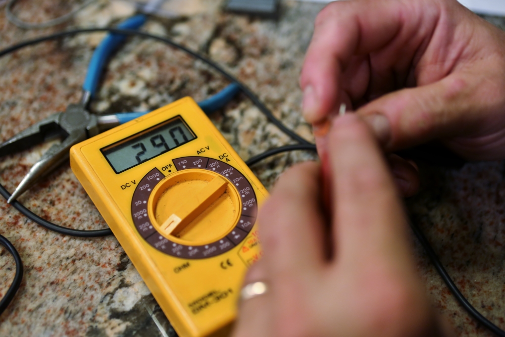
As you can see, the resistance was 290,000 ohms, which is a bit on the high side.
We then tested the five photoresistors we purchased. Here are the results:
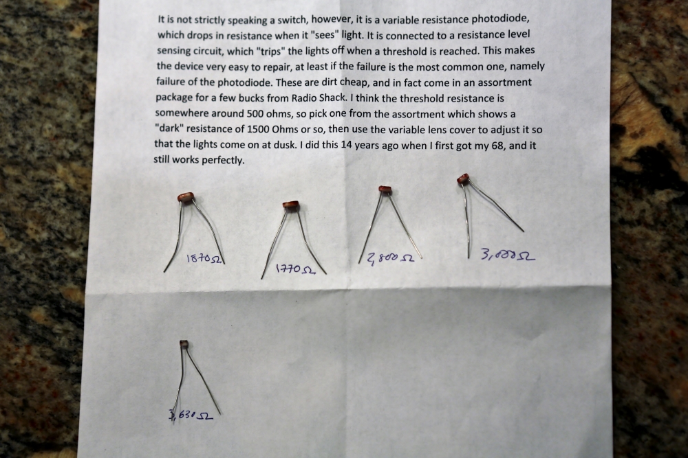
These came in three basic sizes: two larger, two medium, and one small. We decided to use the one with the least resistance; hopefully it will be low enough. Keep in mind that the resistance shown is with the photoresistor uncovered; when they were covered they all went to infinite resistance. It follows that the readings shown are useful for comparison only, because the more light, the lower the resistance. These readings were taken in our kitchen in the evening. On a sunny day, they would presumably read lower.
We selected the one with the lowest resistance, because we have a device to limit its exposure to light built into the sensor.
Once we made our selection, we test-fitted the photoresistor into the sensor housing:
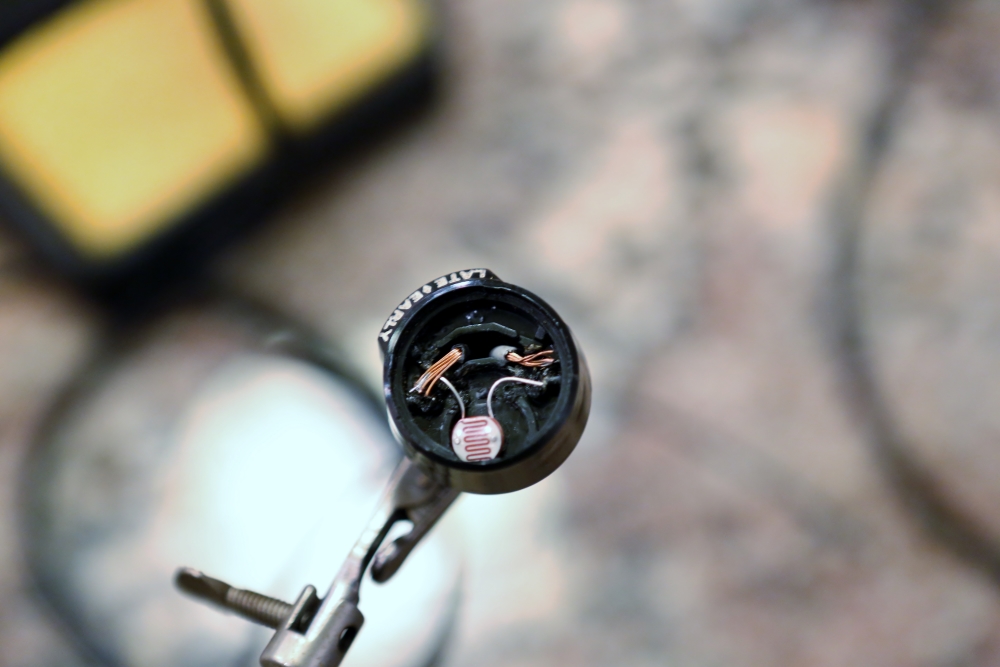
The wires aren't yet lined up in this picture but I was mostly testing the lead lengths for the resistor.
That done, we pulled the wires out of the housing so as to not melt the plastic and soldered them to the resistor.
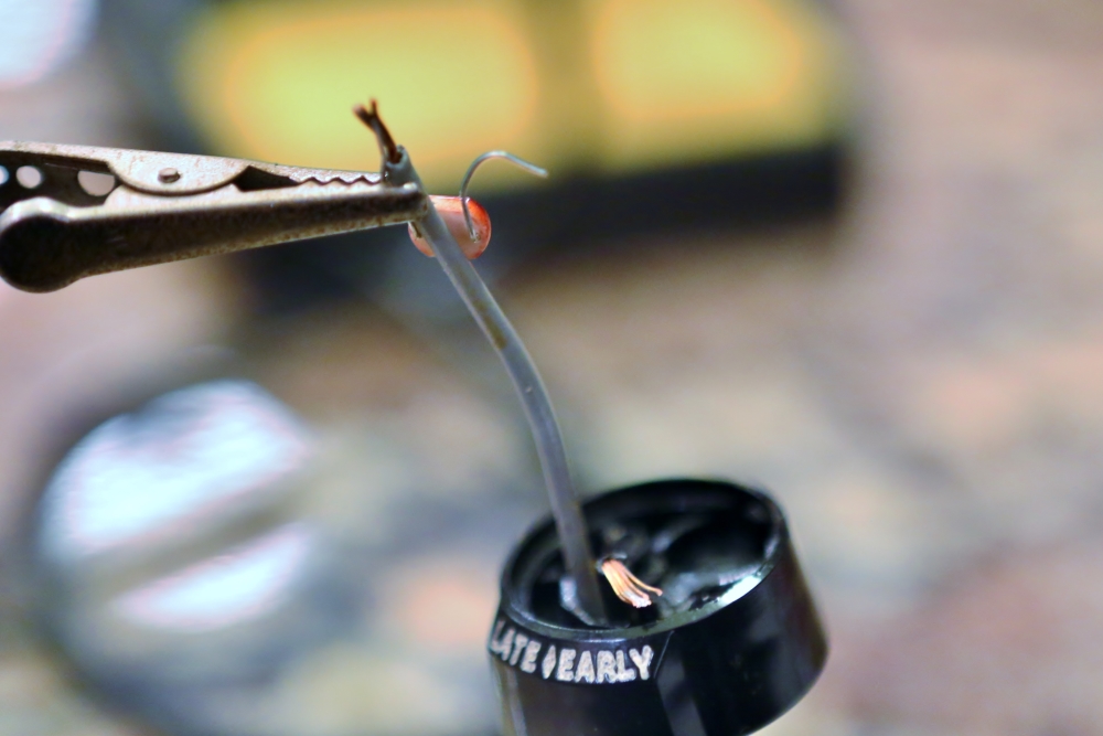
We then put the sensor back in the housing. I decided that we would not glue or cement it in place because once the cover was installed, it seemed to stay in place without difficulty, and if I find out the photoresistor was not appropriate, I want to be able to pull and replace it.
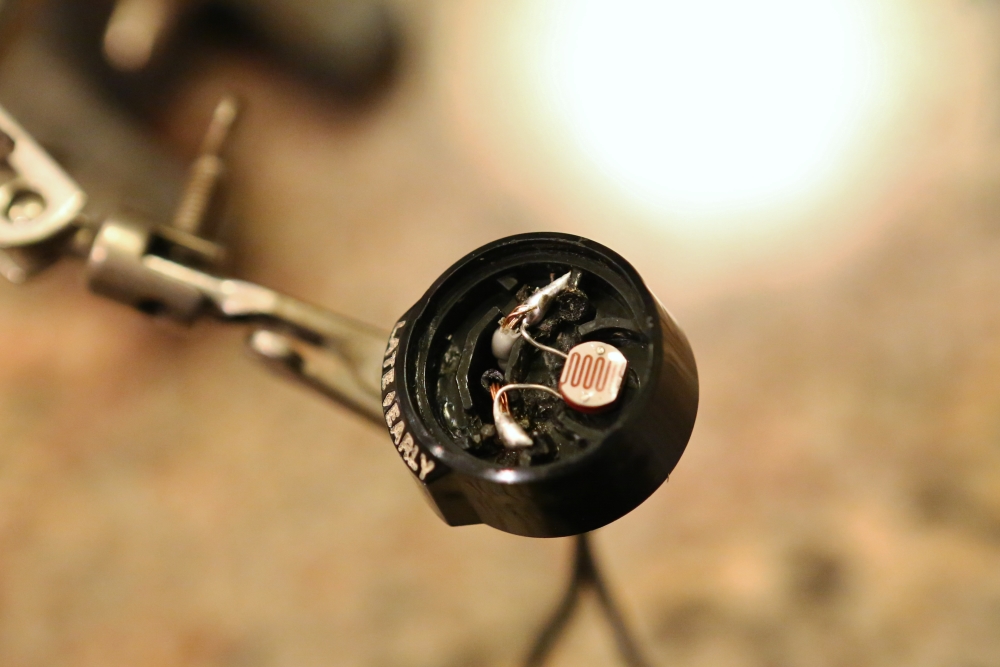
This resistor is smaller than the original one. However, as you can see, it fills the window on the cover.
If the cover is moved all the way to the early position, almost none of the resistor can be seen. This would give a pretty wide range of control over the circuit.
We then installed the sensor back in the car.
It will be awhile before I can test its operation because I need to get the rest of the dash reassembled. I will update once everything is complete.
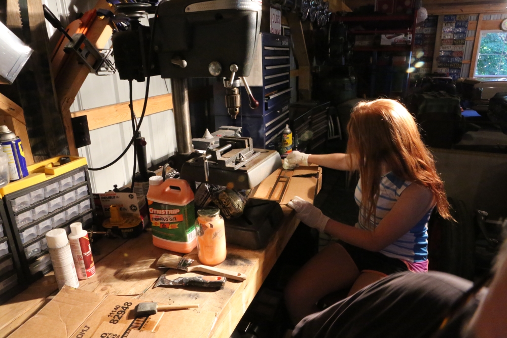
BRONZE REFINISHING
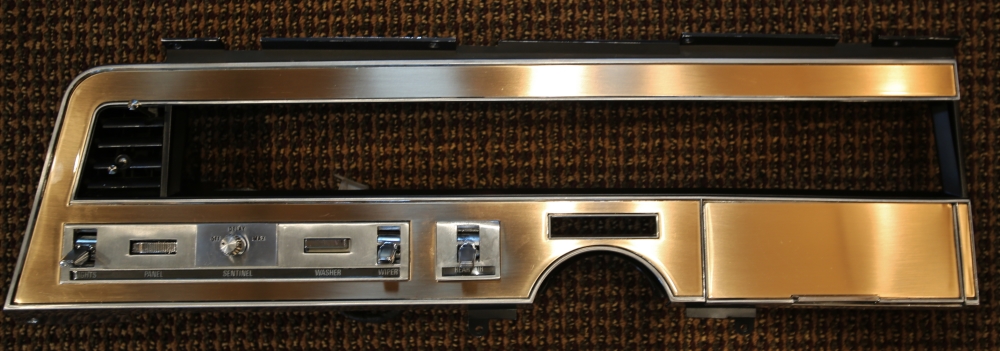
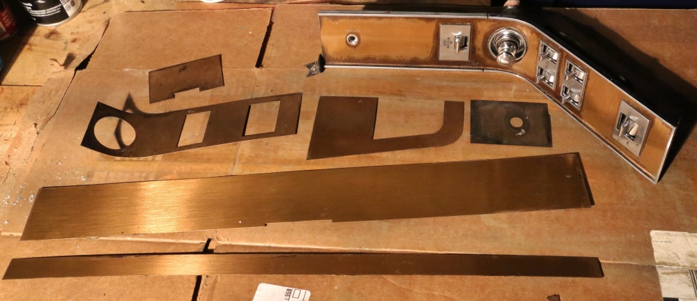
Since we have the cluster out and are messing with everything else, Caty and I decided that we should refinish the bronze panels over the instrument panel portion of the dash. Eventually, we will work our way all around the interior. There are three pieces of bronze on the panel above the instrument cluster. One is the big piece around the cluster, the second is on the ashtray door, and the third is a tiny sliver next to the ashtray. We're pretty much following the instructions found on the Imperial web page. Here's the link.
I had previously removed the bronze panels from the dash, so the first step tonight was stripping off the old finish. This was quite easy; the Citrus Stripper I got at Home Depot did the trick no problems.
Stripper being applied:
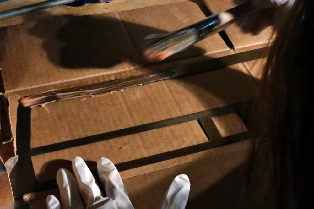
The stripper bubbles up as it releases the coating on the metal:
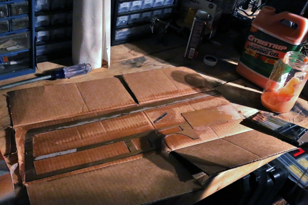
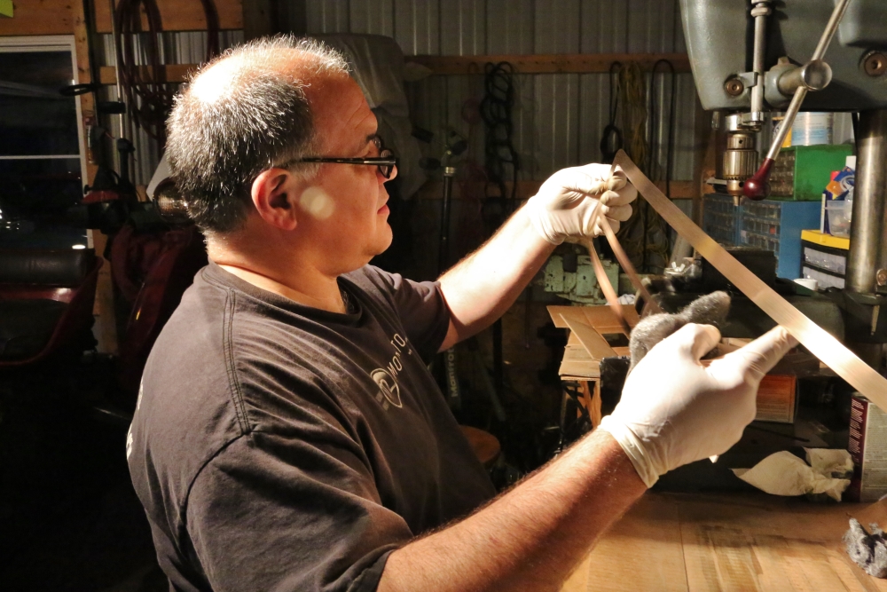
Once we cleaned off that residue, it was time to get to work with the tarnish remover and steel wool. The panels have enough oxidation that we are going to have a ton of elbow grease getting them clean. We started with the Gillespie tarnish remover.
We then proceeded with the 00 steel wool. After scouring the big piece for awhile, we decided to try the tarnish remover again.
Eventually, they started to gleam. Some additional polishing with 0000 steel wool, and it was time to prep them for lacquer.
We used the prep that Gillespie supplied with their kit. It's important to do a thorough job with this. I didn't the first time and I ended up stripping the ashtray door and starting over.
Once the panels were buffed dry, we used a tack rag and canned air to get rid of any dust. Finally we clear coated them with the sealer provided by Gillespie in their kit. I will probably recoat them in a day or two but I would like the finish to harden first.
June 28, 2013 Update
Grrrrrrr. Like it has to many others before me, this has become anathema. I have found a series of ways to screw this up. My plan to deal with any dust was to sand with 2000 grit wet/dry paper, clean the surface, and respray. I would also sand the final coat with 2000 and then polish the surface with a mild compound. The first problem I ran into was that the cleaning agent I used, SEM Solve, attacked the finish. Strip and start over. The next cleaning agent I used, Acryli-Clean, did the same thing. Strip and start over. Ok, so I will try shooting the second coat over the first coat after 30 minutes and then just sand that and polish. The second coat blushed like a school girl in an NFL locker room. Strip and start over. I talked to my body man, Bob Reeve. He says the blushing resulted from high humidity, so I should paint inside, and that I should clean between coats with water with a little dish detergent. The first coat goes fine. I scuff as needed, wash with dish detergent, and spray the second coat. I didn't do a good enough job getting water off and I get more blushing. Strip and start over. I let the thing sit for a couple of days. I need a couple of bushels of patience. Tonight, I stripped it off, cleaned the metal, dried it with a hair dryer, and sprayed it. Apparently I didn't do a good enough job cleaning because I have a lot of crazing. Tomorrow I will...you guessed it...strip and start over.
I think a big part of my problem is that I try to do all three pieces in one evening after work. After a long day at the office, I just want to get done. Once the parts are stripped, I have to go all the way to paint before it's time to crash, so I am racing the clock. As a result, I don't take as long as I should, and therefore my prep is inadequate. So tomorrow is Saturday, and I will start this in the morning. I will start with just the ash tray door and the little sliver that goes next to it. I will go really, really slow. Hopefully, I will have learned a little bit. Hopefully, I will get a good first coat.
The good thing about tonight's experiment is that I got very little dust. I blew everything off carefully with the hair drier and then went over it with a tack rag. So that might be a part of the solution. Another nice thing about the hair drier is that it does cure the lacquer pretty quickly.
Let's hope tomorrow goes better.
July 3, 2013 Update: The Secrets of the Bronze Revealed!
Ok, so those of you who are on the Imperial Club email list know that I have been at wits' end trying to refinish this crazy bronze. Let's put that on hold for a moment.
I've known Bob Reeve for years. He's painted three cars for me and done a lot of other miscellaneous body and paint work, and he focuses on vintage cars. I even used him as an expert witness in a case once. He recently moved his shop to a new location in Jackson, about 40 minutes from here. Wait. Let me back up.
My youngest son Seth graduated from Lansing Christian High School this year. A couple of years ago he discovered SketchUp and has become very proficient at designing things--mostly vehicles--in that 3-D modeling program. He is going to be attending the College For Creative Studies in Detroit next fall and majoring in Transportation Design. CCS has one of the leading Transportation Design programs in the country and it's entirely possible that Seth could wind up working for one of the major auto companies as a designer some day.
So we agreed that it would be good for Seth to work for Bob this summer. Seth could get some valuable experience and maybe learn a thing or two about how real cars are built. This worked out and three days a week Seth is now driving to Jackson and learning to sand.
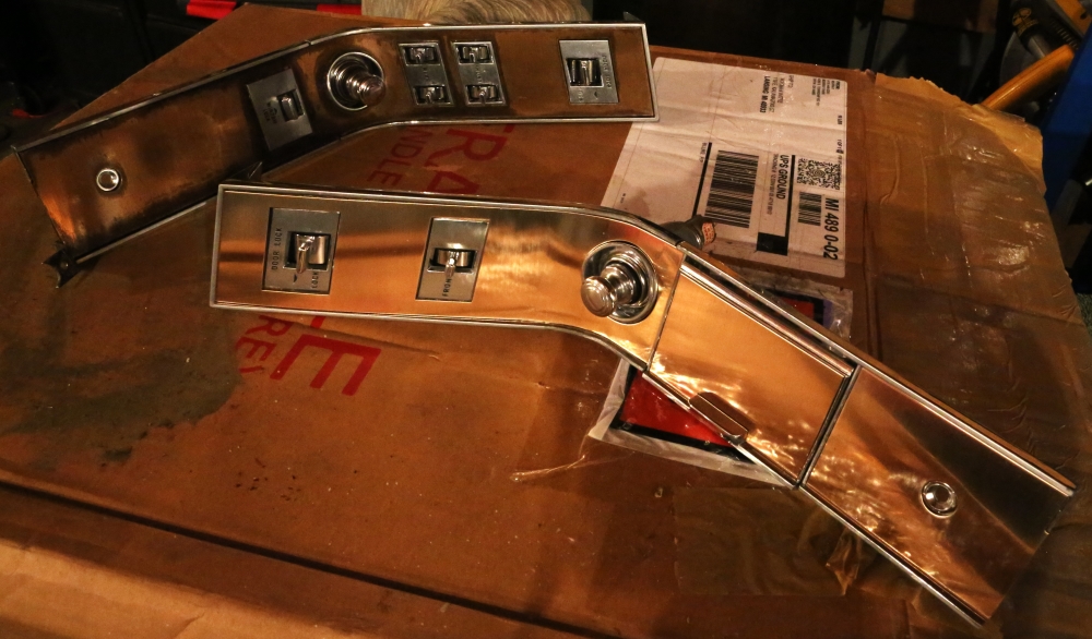
Back to the bronze problem. I've
called Bob several times trying to figure out what on earth I have been doing
wrong, and with Bob's help, I finally solved the problem of how to get a good
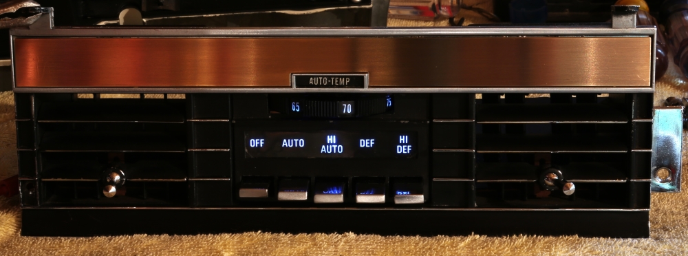
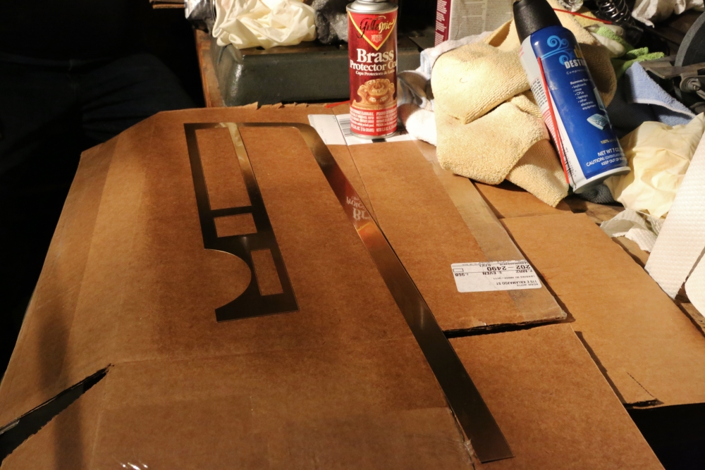
finish on the parts. Here are the outstanding results:
(That's my fingerprint next to the rear air control, not a flaw in the finish.)
So, you might ask, what is the trick? I'm about to tell you. Ready? Here goes:
-
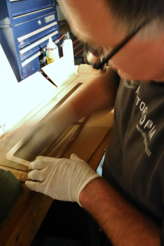
Carefully steel wool the parts so that they have the correct finish. Make sure that there are no scratches or blemishes.
-
Tape them to a piece of cardboard.
-
Put the cardboard with the pieces taped to it in the trunk of the Aura.
-
The next day, call Bob and tell him to take the parts out of the trunk of the Aura.
-
Wait one day.
-
Open the trunk of the Aura, and take the fully finished parts out of the trunk.
-
Voila!
Yes, I am a genius.
A couple of other notes. I did repaint the bezel around the instrument cluster, which had become quite scratched up over the years. I used a satin black which had the appropriate low luster look. I think it came out nicely.
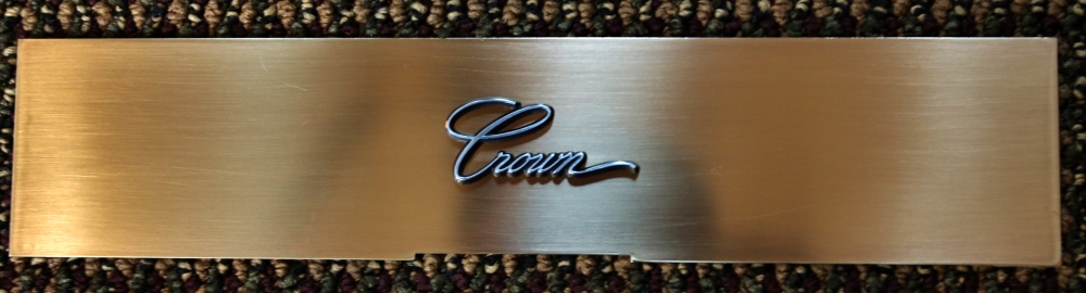
I used the recommended 3M adhesive referred to on the Imperial Club website for this project. It's not cheap, but I like how it works. It comes in small sheets that you trim to fit. You peel the paper backing from one side of the adhesive and stick it on the back of the trim piece. Once you have covered the back of the work, you peel the plastic backer off of the strip and it leaves just the glue on the part. You can trim it down to small pieces, as I did with the Crown emblem on the radio cover door.
One final comment. I haven't had a chance to talk to Bob yet, but I think he used a poly clear that seems much more durable than the lacquer I was using. I am hopeful that this hard finish will hold up well for years to come.
A final, final comment. Or
two. I am going to be sending the rest of the pieces to Bob over the
coming weeks. And I got my fabric from SMS for the front seat
yesterday. The front seat will be reupholstered over the winter.
Here is the fabric, which matches the original material perfectly:
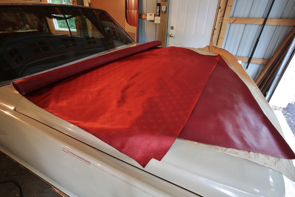
The interior of this car is going to be so cool!
July 8, 2013 Update
The Fourth of July weekend was maddening. My dash trim is finally finished and I am ready to start putting the instrument panel together, but I couldn't work on it because the entire extended weekend I was out of town visiting relatives.
Sunday night I got home, mowed the yard as quickly as possible, and got to work on the bronze project. I've decided that my short-term goal is to get the entire arc of the dash done, from the the driver's arm rest to the passenger arm rest. So the remaining pieces to complete are the three pieces on the passenger door switch console, the one on the driver's door console, the two pieces on the glove box, and the A/C surround on the passenger side.
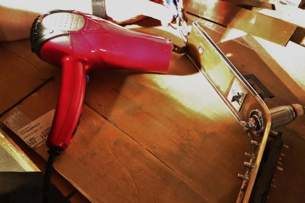
Most of these pieces popped off without too much difficulty. The one that fought the most was the large piece on the glove box door. It turns out that it had come off before and someone had reattached it with silicone caulk.
I borrowed a trick from the Imperial Club web page, and used a hair drier to heat it enough to pull it off.
Here are the pieces that need to be refinished:
The parts from the passenger arm rest were horribly tarnished. I had stripped the old lacquer off them before I took this photograph.
I used the hair dryer to get the trim off the driver's console:
Before going to work on the front of the pieces, I cleaned the old adhesive off the backs, and sanded them with 400 grit paper to leave a clean, even surface for the adhesive:
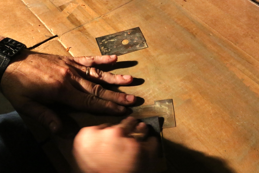
I used the Gilmore's tarnish remover, 2000 grit paper, a Scotchbrite pad, 00 steel wool, and 0000 steel wool on the pieces from the passenger door. Here is a picture of those pieces temporarily put back in place and the driver's console for comparison. These pieces have not been clear-coated yet:
Compare the piece in the foreground with the round hole in it to the one four pictures earlier on this page. If you look closely you can still see some pits from where it was tarnished. I suppose that I could have taken the whole part down with 400 grit, and then come back up to the steel wool, but I think that the pitting will be barely noticeable, if at all, and my goal is excellent driver, not concours restoration. You pays your money and you takes your chances.
These will go to Bob on Tuesday and hopefully I will have them back on Wednesday. I talked to Bob for awhile this morning and he says I am into him for $75 so far, which seems pretty reasonable to me. He is using an automotive polyurethane clear. He put three coats on the parts and noted that this finish is very sensitive to dust because you're painting something shiny over something shiny, instead of painting over a dull basecoat. The clear dries very hard and is very durable. I'll be surprised if I ever have to refinish these again unless I do something really stupid to put a scratch in it. That's entirely possible, of course. He said that the paint that I was using was junk and that it was actually throwing bits of dust into the finish. He said that it was impossible for me to get a satisfactory finish with what I was using. While I know that the tutorial on the club site refers to Gillespie products, I think that company is no longer in business, or at least that brand no longer exists. The stuff I got was clearly old stock, and I do not recommend it.
Looking forward to posting pictures of the installed trim later this week.
July 17, 2013 Update
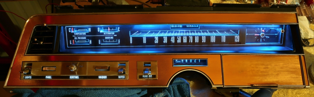
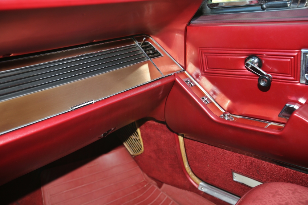
The bronze is now completed for the dash and front door consoles and is installed, so it is time for pictures of the completed installation. You can also see the LED dash lights in these shots. Here's a panoramic shot of the entire dash:
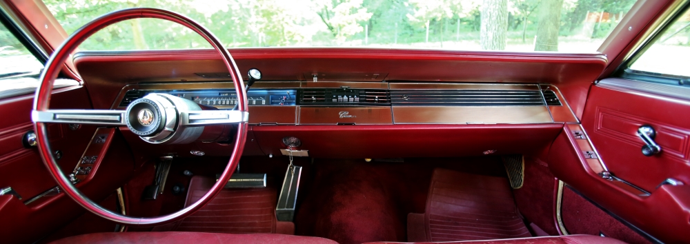
The dark spots on the radio door are the reflections from the vent lever and right vent lever blank on the underside of the dash. It's really bugging me that I didn't straighten the passenger side floormat first. Please find it in your heart to forgive me.
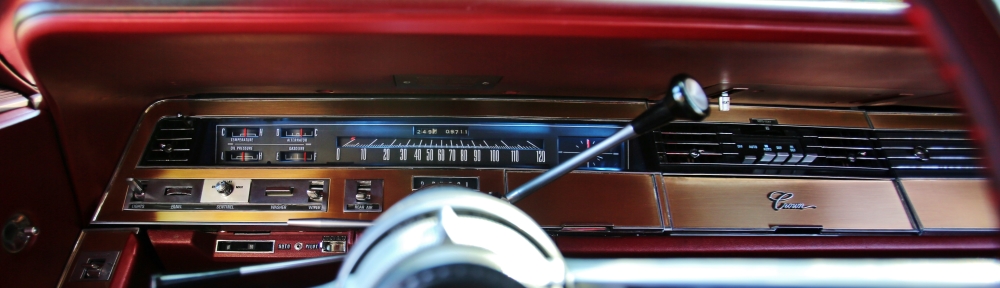
Here is a close up of the instrument cluster:
This shot shows the driver's door console:
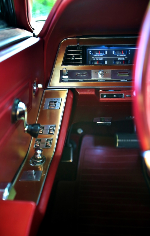
Compare the picture above with this one.
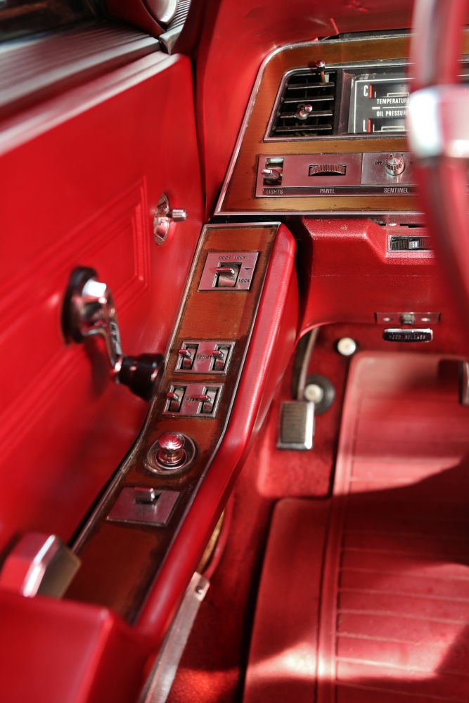
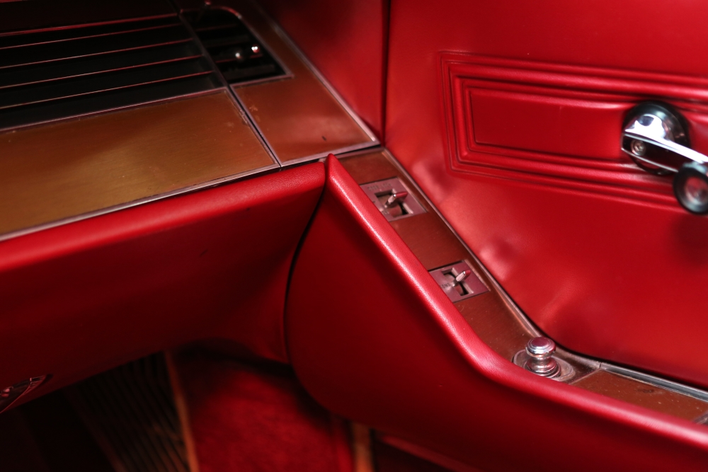
And here is the passenger side of the dash and passenger door:
Here's your comparison shot.
So that's it for the dash project. I think I will add a few shots to the gallery at the end of my Imperial Story and call it a day.
My Imperial Story: Why I needed another tank
Data: info on the new yacht
Imperial Heart Surgery: freshening the motor, and some other stuff
Norman C. Witte Personal Web Page Command Center